Slip Ring Mechanical Integration Guide: Dimensions, Mounting, and Cable Routing
Plan slip ring mechanical integration with clear dimensions, bore requirements, mounting interfaces and cable routing before sending an OEM RFQ.
2026-09-19 13:55 by admin
- Share
-

-

-

-

-

Slip ring mechanical integration requires more than matching a body diameter to an opening. OEM engineers need to confirm the installation envelope, the fixed and rotating interfaces, and the complete cable route. A candidate must fit during operation, remain accessible for assembly, and leave enough room for the actual connectors and cable bends.
Begin with the surrounding machine geometry, then compare the proposed slip ring configuration against that space. A clearly defined interface helps the supplier review fit without guessing which dimensions are hard limits and which parts of the machine can change.
Define the installation envelope before comparing dimensions
The installation envelope is the space available for the complete installed assembly, including protruding fittings and routed cables. Outside diameter and overall length are starting points, but they do not describe access for fasteners, connector mating, or removal. Define the machine's restricted space before treating catalog slip ring dimensions as proof of fit.
Record the allowable radial and axial space from a common reference, such as the rotation axis and a mounting face. Include nearby brackets, covers, fasteners, and moving structures. Mark any local opening or recess that makes the available space different from a simple cylinder.
Ask what each quoted length includes. Body length, flange-to-end length, and length with a connector or cable gland are different measurements. A comparison is useful only when the measurement endpoints match.
| Space to check | Include in the review | Question the check answers |
|---|---|---|
| Installed space | Body, flange, cable exits, connectors, and fixed supports | Does the complete assembly fit in its operating position? |
| Assembly and service access | Insertion path, fastener tools, connector mating, and removal path | Can the unit be installed and serviced without an unforeseen obstruction? |
| Space occupied during motion | Moving members and cable routes throughout the intended movement | Does the assembly remain clear of surrounding geometry? |
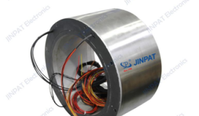
JINPAT's capsule selection material lists outside diameter and length separately, while its LPT through-bore table separates internal and external diameters. Those fields help narrow candidates. The tables alone do not establish connector access, mounting clearances, or the complete installed envelope of a specific configuration.
Specify the through-bore requirement and its reference
A through-bore requirement should identify what passes through the center and how the assembly will be installed. The shaft or service bundle in the final position may not be the largest object that must pass through during assembly. Specify the required passage and interface conditions instead of selecting through bore size from a nominal shaft dimension alone.
Identify whether the bore surrounds a shaft, provides a route for services, or has another machine-specific purpose. State whether the object inside the bore moves relative to the surrounding slip ring member. A hollow center does not by itself define a locating fit, a bearing function, or an approved attachment method.
For an assembly that must pass over a shaft shoulder or a preassembled connector, describe that installation sequence. If a part can be removed before installation, identify the dependency rather than assuming assembly staff can take the machine apart later.
Keep fit and clearance requirements explicit. Reference the mating component and let the responsible designers agree the applicable tolerances and alignment requirements. Do not invent a universal clearance allowance or combine one model's bore with another model's outside diameter. A retrofit should reference the actual mating geometry and its revision, not merely the label on the old unit.
Describe mounting as a relationship between machine parts
A mounting specification should show which slip ring member moves with the machine and which member is restrained, together with the interface for each. Labels such as flange, shaft, or housing mounting do not establish the full arrangement. Identify the locating surfaces, fasteners, and reference geometry so both sides of the rotating interface can be reviewed.
Identify the fixed and rotating members
Mark the rotation axis and identify the machine component attached to each member. Use the supplier's rotor and stator designations consistently; do not infer the arrangement solely from which component looks like the outer housing. Show how the stationary member is restrained and how its cables remain with the stationary structure.
The intended mounting or anti-rotation feature should provide the restraint, rather than tension in the electrical leads. Follow the approved configuration's mounting instructions. Do not assume the slip ring supports external shaft loads just because the assembly contains bearings or surrounds a shaft.
Define the flange, shaft, or housing interface
For flange mounting, identify the mating face, locating feature, mounting-hole pattern, and access to the fasteners. State hole quantity and positions, thread or clearance-hole requirements, and the viewing direction used to describe the pattern. An angular orientation without a defined reference can produce a mirrored or rotated interpretation.
For a shaft interface, describe the relevant diameter, shoulder positions, available engagement, and intended attachment arrangement. For a housing interface, show the approved locating or support surfaces and any restriction on where the body may be supported. Avoid specifying clamp positions or tightening torque without the applicable product instructions.
Keep essential relationships on the same interface view. A list of dimensions without datums leaves the supplier to guess which surfaces control position and alignment. Identify who owns each mating feature and which interface dimensions are already frozen.
Plan cable exits and connector orientation together
Cable exit direction, lead length, connector orientation, and bend space form one routing problem. Specify the route separately for the fixed and rotating sides, including where each cable is supported. A connector can fit in its final position yet remain impossible to mate, so include access and the assembly sequence when reviewing the available space.
Describe axial, radial, or angled exits relative to the slip ring axis and a named face. For an exit at a particular angular position, define the viewing direction and reference feature. “Cable exit on the right” is ambiguous when the assembly is viewed from opposite ends.
Specify lead length along the intended route and agree the measurement endpoints. Include the connector or termination arrangement, required free lead, and strain-relief location. Do not measure only the straight-line distance between the slip ring and the destination. Any service allowance should have a defined purpose and should not create loose cable near moving parts.
JINPAT's through-bore material describes rotor and stator outlet and lead-length customization, as well as dimensional adaptation subject to structural constraints. Its capsule Ethernet material lists connector types among the customization options. Those statements support discussing interface requirements; they do not confirm that every exit position, connector orientation, or requested dimension is available on every model.
Reserve space for the actual cable bend
Use the selected cable manufacturer's minimum bend-radius requirement for the relevant installation condition. A fixed bend and a repeatedly moving bend are not interchangeable cases. The igus explanation of cable bend radius distinguishes fixed, flexible, and cable-carrier use. Its guidance supports checking the application rather than assigning one generic radius to every cable.
Include the bend and the connector backshell in the space review. Show the planned support point so the route does not depend on forcing a tight bend immediately at the outlet. Where the cable moves, check the route throughout that motion; where the cable remains fixed, keep it clear of adjacent rotating components.
Catch mechanical integration mistakes with an assembly example
Mechanical integration errors often come from checking a single dimension or a single assembled position. Review the full installation sequence and the neighboring parts together, then identify which constraint causes a clash. Resolving the actual obstruction is more useful than asking for a smaller slip ring without explaining where the original arrangement fails.
Consider a hypothetical rotary inspection platform. The proposed slip ring body fits beneath a cover, and the center opening accommodates the intended shaft. During assembly review, however, the cover prevents access to a connector latch, while a cable support forces the lead to turn sharply at the outlet. This is an illustrative engineering example, not a customer case or a verified JINPAT installation.
The team should check whether the support position, mating sequence, or cover access can change. If the machine interfaces are fixed, the supplier needs those constraints before evaluating a different cable arrangement. Reducing body diameter alone may leave both problems unresolved.
| Integration mistake | Why the initial fit check misses it | What to communicate instead |
|---|---|---|
| Checking only body dimensions | A gland, backshell, or cable bend extends beyond the body | The complete installed outline and restricted areas |
| Matching the final bore clearance only | A shoulder or connector blocks the insertion path | The largest assembly obstruction and installation sequence |
| Sending a hole pattern without its reference | The same pattern can be interpreted in a different orientation | Mating face, datum, viewing direction, and angular reference |
| Measuring lead length as a straight line | The supported route is longer and includes bends | Route endpoints, supports, bend requirements, and termination |
| Checking only the parked position | A moving part or cable enters the occupied space later | The relevant movement range and surrounding geometry |
Communicate the mechanical boundaries before RFQ
A mechanical RFQ description should separate fixed machine interfaces from adjustable design choices. Provide the available envelope, mating geometry, member relationships, and cable route with consistent references. Identify unresolved interfaces openly so the supplier can respond against the actual constraints rather than approve an incomplete outline that appears to fit on paper.
Before requesting a quotation, confirm that the interface description answers the following mechanical questions:
Which diameter, length, and passage constraints are mandatory, and where are they measured?
Which member attaches to each machine component, and what locates or restrains it?
Can the mounting fasteners and connectors be reached in the intended assembly sequence?
Where do the fixed-side and rotating-side cables exit, bend, terminate, and receive support?
Which neighboring components or interface revisions still need to be confirmed?
Discuss the proposed interface with JINPAT using those boundaries, and request confirmation for the applicable configuration before freezing the machine design. For the remaining electrical, operating, and project information, use the slip ring specification checklist for an RFQ.