How to Define a Slip Ring Motion Profile: Speed, Duty Cycle, and Rotation Type
Define slip ring speed, duty cycle and rotation type with a clear operating sequence. Give suppliers the motion conditions they need before selection.
2026-09-19 13:41 by admin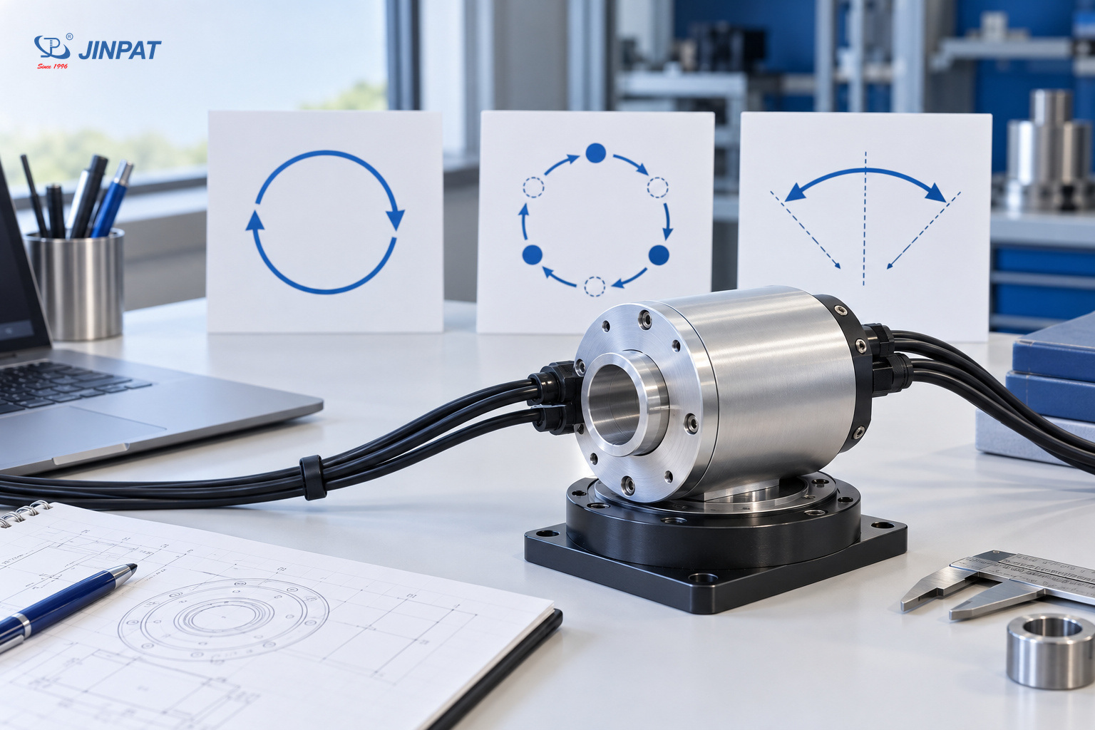
- Share
-

-

-

-

-

A slip ring motion profile describes how the rotating assembly moves over time: its direction, operating speed, acceleration, stops and reversals. Define that sequence before comparing a catalog speed rating with your application. A single maximum RPM does not explain whether the machine runs continuously, indexes between positions or repeatedly reverses within a limited angle.
For OEM engineers, the useful output is a short operating sequence that a supplier can evaluate alongside the electrical load and installation conditions. Keep the motion description distinct from those other specifications, while identifying when they occur together.
Start with the rotation pattern, not the highest RPM
Classify the motion as continuous, intermittent or oscillating, then describe the actual sequence within that category. Continuous rotation describes the motion pattern; it does not necessarily mean the equipment operates all day. Intermittent rotation includes stops, while oscillating motion reverses within a defined angular range. State the reference direction and operating modes explicitly.
The distinction matters because identical maximum speeds can hide different operating patterns. An indexing station may rotate briefly and remain stationary during a process. A positioning mechanism may return across the same angular range. A continuously rotating platform may still stop between shifts.
| Motion pattern | Information to provide | Ambiguity to remove |
|---|---|---|
| Continuous rotation | Direction, normal speed range and uninterrupted running periods | Whether rotation continues throughout the operating shift |
| Intermittent rotation | Move duration, stop duration and starts per operating period | Whether idle time is included in the stated duty cycle |
| Oscillating motion | Angular endpoints, reference position, reversal sequence and dwell | Whether the quoted angle is total travel or travel on each side |
| Multiple operating modes | Production, setup, cleaning and recovery sequences | Which mode defines the most demanding movement |
If a machine combines these patterns, list the modes separately. Do not choose one convenient label and leave the supplier to infer the others.
Separate normal speed from peaks and transitions
Specify the normal slip ring speed range and identify any higher speed, its duration and the mode in which it occurs. Describe acceleration, deceleration and direction changes as part of the sequence. A maximum speed entry should tell the reviewer whether it is a sustained operating condition, a short event or a design boundary.
Use a speed-versus-time sketch if a written description becomes difficult to follow. Label the axes and units, and identify repeated segments. For oscillating equipment, an angle-versus-time sketch can also clarify endpoints and dwell. These sketches are requirements illustrations, not evidence that a selected slip ring has been qualified for the motion.
A motor's nameplate speed is not automatically the slip ring's operating speed. Describe the motion at the slip ring interface, accounting for the machine arrangement. Similarly, a controller limit does not establish the actual normal operating profile.
Include exceptional modes that the assembly must accommodate, such as setup jogging or a defined recovery sequence. If a mode remains undecided, identify it as an open requirement rather than presenting an assumed value as final.
Define duty cycle with an explicit time basis
State slip ring duty cycle as an operating schedule with a clear time basis, including moving periods, stationary periods and planned shutdowns. Separate rotational duty from electrical loading: a stationary assembly may still carry power or signals. A percentage alone is insufficient when it hides how long each movement and pause lasts.
Describe a representative cycle first, then explain how often it repeats within a shift and how many shifts the equipment is expected to run. If production demand varies, identify the normal schedule and the demanding schedule that needs evaluation.
The same fraction of moving time can arise from frequent short movements or long uninterrupted runs. Those schedules are not interchangeable descriptions. Avoid converting either schedule into an unsupported service-life prediction.
Keep motion and load on the same timeline
Record whether circuits remain energized during dwell, whether the load changes during movement and whether signals must remain available during stops or reversals. The motion document only needs these relationships; a separate electrical or signal specification should define the actual load and performance requirements.
Do not use rotational duty to justify an electrical rating. Equally, do not assume an electrical duty description tells the supplier how often the slip ring starts, stops or changes direction.
Build a motion record that another engineer can interpret
Create one record per operating mode, using the same terms and reference frame throughout. Include the movement sequence, speed, direction, dwell, repetition and any simultaneous loading that matters. The record should allow another engineer to reconstruct the intended operation without asking what a percentage, angle or maximum speed was meant to describe.
| Record field | What the OEM should enter | Review question |
|---|---|---|
| Mode and revision | Named operating mode and document revision | Is this the current production requirement? |
| Movement sequence | Ordered moves, stops and reversals | Can the cycle be reconstructed? |
| Speed and transitions | Normal range, peaks, duration and transition description | Which conditions are sustained? |
| Angle and direction | Reference view, endpoints and direction convention | Could two readers interpret the motion differently? |
| Operating schedule | Cycle repetition, shift pattern and shutdowns | Is the time basis explicit? |
| Simultaneous conditions | Relevant load, temperature or signal activity by segment | Which requirements occur together? |
| Open items | Unconfirmed modes or machine limits | Who will resolve them before selection? |
In a hypothetical engineering example, an indexing machine moves to a processing position, dwells while its circuits remain energized, then returns to a reference position. Its document should distinguish the outbound move, energized dwell and return. Calling the application “intermittent” would leave important parts of that sequence unstated. This is an illustrative example, not a customer case.
Compare the profile with the proposed configuration
Use the completed motion profile to ask whether the proposed slip ring configuration covers the actual operating modes, rather than treating a catalog speed entry as a complete application approval. Confirm the relevant configuration and the conditions attached to its rating. Keep service-life expectations separate from evidence that a specific operating sequence has been evaluated.
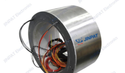
JINPAT's through-bore selection document lists rotating speed as a mechanical parameter, separately from electrical and environmental entries. That separation is useful when preparing an inquiry: speed is one field in a broader configuration review, not a substitute for the rest of the application description.
The document alone does not establish qualification for your start-stop sequence, reversal pattern or intended operating schedule. Ask which assumptions the proposed selection uses and whether additional evaluation is needed for an unusual mode.
Avoid adding an arbitrary speed margin and calling the selection complete. Likewise, do not translate catalog revolutions or a general longevity statement into years of machine operation without a relevant basis. These decisions require configuration-specific information and an agreed interpretation of the operating conditions.
Close the motion questions before sending the RFQ
Before requesting a quote, resolve conflicting speed values, undefined angle references and unclear duty-cycle time bases. Send the current motion record with the relevant machine interface information, and identify any open operating modes. The next engineering decision is whether the supplier can evaluate that defined profile or needs further application data.
A useful final review is to ask a colleague to describe one complete cycle using only your record. If that colleague cannot tell when the assembly rotates, stops, reverses or remains energized, revise the description before it becomes an assumption in a quotation.
Ask JINPAT to review the defined motion conditions against the proposed configuration. Once the motion boundary is clear, use the slip ring specification checklist for OEM engineers to connect it with the remaining RFQ requirements. Keep the motion record as a referenced attachment so later design changes can be reviewed against the same operating sequence.